NanoVNA as a RLC meter
Building anything RF-related, like filters or amplifiers for ham radio, you quickly find you need a way to measure capacitors and inductors, especially homemade ones like air-wound coils. You can use online calculators to get the number of windings, but there are just too many variables that affect the result.
You will also find the value varies with the operating frequency, this is normal and fine if the change is not too fast. I never really thought of this and kind of ignored things like parasitic capacitance, but you can’t get away with that at RF.
High quality components vary less, but none are perfect. When choosing components for a build, it’s good to check their response at the operating frequency, even if they have something written on them. I had some cheap capacitors that simply stopped being capacitive above a few MHz.
I recently bought a NanoVNA and spent some time figuring this out. Guides on YouTube were more misleading than helpful but it’s surprisingly easy in the end
Note: I use the program NanoVNASaver for this, as I find the device’s display too fiddly to use.
To keep it short, here’s a list of things to do to get accurate readings:
Preparations
- Connect the NanoVNA to the NanoVNASaver running on a PC. Make sure it detected it, then hit Connect.
- Some NanoVNA models let you choose the number of samples, between 101 and 401. The app does not remember this, I always have to set it again. You do that in the device settings dialog called “Manage”.
- Set your VNA to the frequency range you want to operate in. I usually use 1-30 MHz when working with ham radio stuff for the lower bands, then shrink the span when fine-tuning the circuit
- Calibrate your VNA. This is most important when working with small values, like nH inductors. Calibration compensates for stray reactance and losses in your test harness. NanoVNASaver has a calibration wizard for this.
- Calibrate exactly as you will measure, including your test rig, any adapters, cables etc.
- You don’t need the calibrations using port 2 (S12) for these measurements, just skip that part.
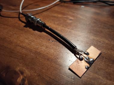
- If you don’t have the calibration standards handy or compatible with your setup (and you probably don’t if you use e.g. screw terminals):
- “short” can be a piece of wire
- “open” is simply nothing
- “load” is two 100 ohm resistors in parallel. This is not quite perfect, but will do the trick.
- Measure the part exactly as it will be used in the circuit. No long leads, for example. You can fine-tune an inductor and then ruin everything by trimming the legs. Also, note that spacing between windings on a coil alters the inductance. If you use a ferrite core, its position inside the coil matters. Some sources claim the position of windings on a toroid also make a difference, but I did not observe this, the effect is minuscule.
Measurement
- Connect the component across the Port 1 (between the coax core and its shield)
- Set your VNA to any of the S11 modes, this means single-port measurement. There are handy presets for our measurement: Series L and Series C
- Run a sweep and move the cursor to the frequency you care about. You can read your component’s value in the values window on the top left (on the NanoVNA itself, it should be near the top of the screen).
- If you want to fine-tune an inductor, choose “continuous sweep”, then the plot redraws as you mess with the windings.
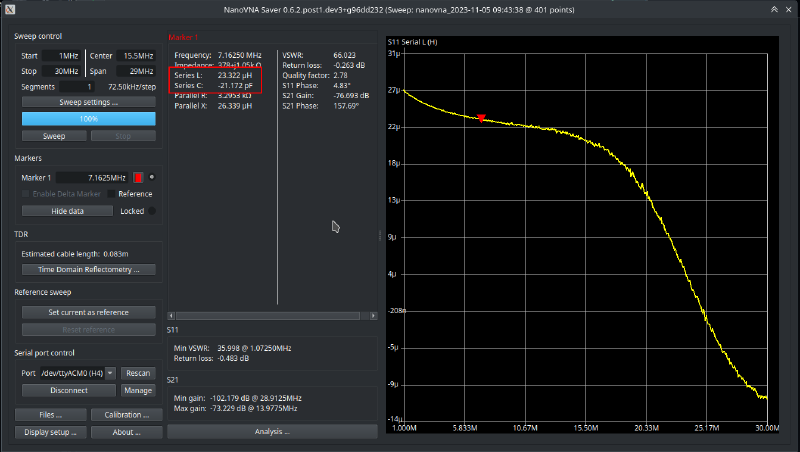
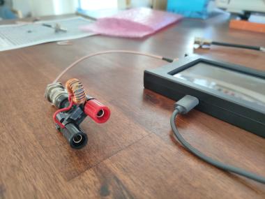
Here’s an example measurement of a 23uH inductor (seen above in the screw adapter) that I wanted to use on the 40m band. It looks fine up to about 15 MHz, the rolloff is probably caused by the material in the ferrite ring, parasitic capacitance between windings, etc.


