First prototype PCB for GEX
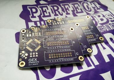
This is just a quick update about the GEX project: the OSH Park PCBs finally arrived, and they work!
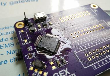
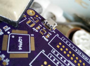
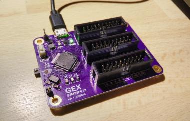
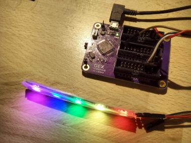
Some pics from the first board’s assembly and testing:
I made some mistakes in the layout, but they were easy to fix, and electrically everything seems to work just fine. No big deal, finding bugs in the schematic is why I made this board to begin with. If it doubles as a useful tool, that’s of course a plus.
This is the first time I tried using a switching regulator (MCP1603); I bought those parts some years ago to try and didn’t get around to do it since. Without load, there’s a rather large ripple (around 100~mV), but after soldering on the MCU which increased the current draw, the ripple mostly disappeared. I believe the regulator switched to some different mode, as the coil hissing also stopped.
If you’re curious about the schematic, it’s here: GEX Hub schematic.
How the board works
- The LOCK button is used to enable or disable the USB Mass Storage FAT16 virtual disk with config files. The settings are stored to flash when the disk is disconnected using the button. (Re-configuration can also be done via the API.)
- There are two LEDs, green and red. The green one is simply connected to the 3.3~V network, the red diode is an indicator. The MCU uses various blinking patterns to indicate what’s happening and when a problem occurs. Normally the LED shortly flashes every 3 seconds to indicate a normal operation.
- The three large pin sockets can be used for attaching flat cable connectors, but they’re also perfectly compatible with jumper wires and headers. I chose those because of their flexibility. The female counterparts are cheap and widely available.
- To upload a firmware update, you remove the jumper (which is “active OFF” to prevent losing it) and flash a DFU image using
dfu-utilor some other DFU flashing utility. This jumper should be on the top side, messing up its footprint is one of the mentioned mistakes; the other is the connector right next to it, or, rather, the lack theoreof, because I got the pitch wrong there as well.
What can GEX do right now?
The project is nearing its completeness, feature-wise; however, some pieces are still missing, and there will be a lot of tuning and bug-fixing to make it ready for the first public release and opening the source repositories to the public. (They’ll use MPLv2, btw).
GEX connects using two bulk USB endpoints to a PC driver, which is currently either ACM (virtual comport) or libUSB via pyUSB. Python is the main way to work with GEX; there’s also a basic C support, and a MATLAB support is also in the queue. It would certainly be nice to support LabView, but I don’t know anything about it so I won’t attempt that before everything else is reasonably complete.
So what’s ready? A lot, actually:
- Digital output
- Pulse generation (microsecond and millisecond precision, based on length), configurable polarity, available on all output pins
- Digital input with pin change events
- NeoPixel RGB LED strip driving
- I2C master
- SPI master, up to 16 slaves, multicast support
- USART, synchronous and asynchronous mode, RS485 driver support
- Dallas 1-Wire master (with the bus search algorithm implemented)
- ADC - analog sampling, averaging, block and streamed capture, level triggered capture with pre-trigger
- SIPO driver, meant for parallel output shift registers like 595 or 4094, supports multiple devices loaded in parallel using the same control pins
- Frequency capture - direct and indirect, also pulse length measurement
- Touch sensing - using the STM32 touch-sensing controller. Allows building capacitive touch buttons and other features; this is here mostly as a demonstration of how capacitive touch sensing works
- Simple PWM output - 4 channels with configurable duty cycle, common frequency
There are some limitations and many things will need further polishing, but they work.
Here’s what I want to add next:
- DAC - analog output, ideally with DDS function for waveform generation
- Streamed digital capture (like ADC, but reading a digital port). This could work as a simple logic analyzer. The functionality is already possible using the Digital Input unit, but only for slow frequencies.
- Quadrature encoder input - this can be used for incremental knobs or position sensing using encoder strips and discs
I would also like to have a PWM support for 3-phase motors, but that’s a “stretch goal” for now.
Here’s a photo of how I tested the frequency capture with some more high-tech tools that GEX eventually wants to replace for the “home bench”:

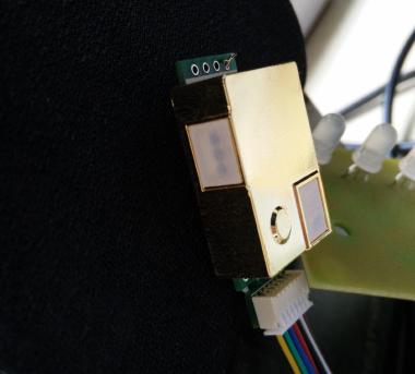
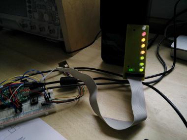
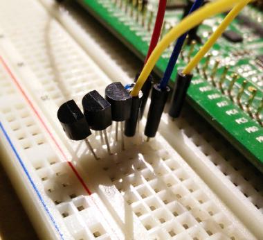
And some GEX experiments - a NDIR CO₂ sensor interfaced using USART, a RG LED display with two 595, and testing the 1-Wire search algorithm with some thermometers. You’ll find some other experiments in the previous articles, all tagged “gex” (put it in the search box).
Thanks for your interest in GEX, and stay tuned for more updates!
If you follow me on Mastodon, you’ll get them in real time - especially because I don’t have a RSS feed here (oops)


