STM32 Touch Sense
GEX has been going steadily forward over the fast few months and is now roughly 80% feature complete; the only notable missing features are PWM output and DAC.
To take a break from the horrors of timer synchronization I went through last week, implementing frequency measurement, I took a look at the Touch Sensing Controller (TSC). There’s not much reason to have this implemented in GEX, as the project is mainly meant to be used as a data acquisition or an experiment automation kit. However, the used principle is interesting enough to warrant a closer look, and it will serve as a nice demonstration.
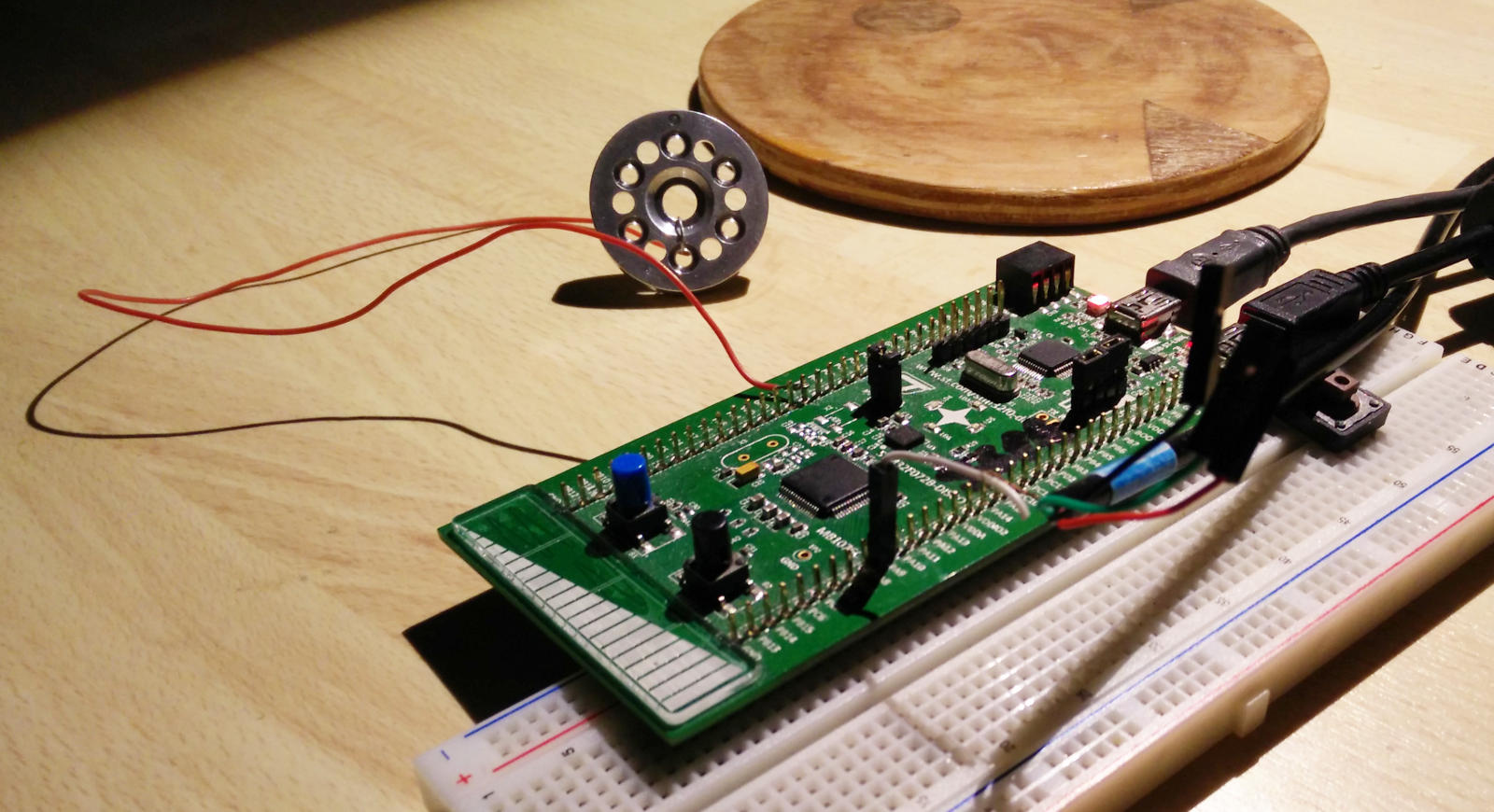
I used the Discovery STM32F072B kit to try this out, the same board I develop the GEX firmware with. It has an “analog slider” demo area on it that uses the touch sensing feature. I couldn’t get it to work too well, so I instead closed the solder jumpers on the bottom of the board and attached an external electrode with a piece of wire.
Principle of Touch Sensing
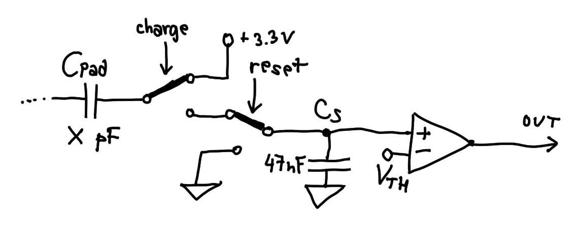
A good explanation of the touch sensing principle can be found in the STM32F072 Reference Manual (en.DM00031936.pdf), chapter 16. It’s based on capacitance measurement using charge transfer. The sense pad forms one electrode of a variable capacitor, the other being the environment. To measure the pad’s capacity, we periodically charge it and discharge into a larger, fixed sampling capacitor, while counting the cycles needed to reach a certain threshold voltage.
Here’s how the measurement goes, taking the STM32F072 discovery board as a reference:
-
The sampling capacitor (47 nF) is discharged by connecting it to the ground.
-
The sense pad is charged to the system voltage (3.3V). This loads it with a charge which will remain after disconnecting the source. The amount of charge depends on the capacitance, which increases when you touch the pad, or even just approach it. With a “capacitor” of this size (couple pF, at most nF), the charging is almost instantaneous.
-
The sampling capacitor, now disconnected from ground and left floating, is connected using an analog switch to the sense pad. The charge moves from the pad to the capacitor to equate their voltages. This, again, happens very quickly, because there’s only a very small amount of charge. Because the sense pad was charged to the full supply voltage the sampling capacitor’s voltage, which started at ground, necessarily increases. This increase is just a couple mV, but it can be measured.
-
The control circuitry then disconnects the capacitor and repeats the cycle from step 2 (in the diagram above this corresponds to flipping the left switch). After each loop, a counter in incremented by 1. The loop stops once the voltage on the sampling capacitor reaches a threshold defined by a voltage comparator. This is somewhere around half of the supply voltage.
-
Finally, we retrieve the value from the counter and either compare it to our defined threshold (e.g. a touch is detected if the number is less than 500), or use it as an analog input. The raw counter value can be used with some extra math to create touch sliders, spinners and other features.
STM32 Gotchas
Nothing is ever easy, is it? The STM32F072 has a touch sensing controller; incidentally it’s the same IP you will find in some STM32L4 chips. The controller works well, but there are several steps and rules you need to follow, or it just won’t work. The controller consists of 8 groups, each of 4 pins. One pin must be dedicated to the sampling capacitor, while up to three of the remaining pins can be used for touch sense pads.
Now, I would expect to configure some registers, set an alternate function and be done with it. Wrong. You must configure the pins in a particular way, and also manually discharge the capacitors before each measurement.
- The capacitor pin must be configured as Open-Drain
- The capacitor pin also must have its Schmitt trigger function disabled.
- The sense pins must be configured as Push-Pull
All three functions could happen automatically, but they just don’t. In particular, the Schmitt trigger disabling is strange, as the capacitor pins are configured in a different register and never change during the operation. It looks like a design oversight to me. Anyways, if you get the setup right, it can work quite well.
You can read some more tips and details in the Training slideshow (slides, presenter notes)
The measurement is performed as follows:
- Manually discharge the capacitor by clearing the
IODEFpin in theCRregister. The recommended discharge time is 1 ms, but you could use a shorter time, depending on the sampling capacitor size. - Set
IODEFhigh if the pads are interlaced, or leave it cleared if they’re separate (for push-buttons). This controls all configured touch sensing pins other than the one channel (pad) currently used. (if this gets confusing, consult the reference manual or the slides linked above). - Select the channel you want to sample in the
IOCCRregister. Only one channel can be enabled per group (or they will be added together), but you can sample up to all eight groups at once. - Start the measurement loop using the
STARTbit in theCRregister. - Wait for the completion flag, or an interrupt and read the counter values.
If a pad is faulty and the charging takes too long (you can configure the threshold, as well as the various timing parameters of the sampling loop), the error flag will be set and the measurement aborted. This is to prevent the loop going forever.
Scope Screenshots
I wanted to see how this all works with my own eyes, of course. You need a 1:100 probe for this if you don’t want to affect the sensitive circuit by merely probing it. 1:10 will show something, but the readings will be significantly distorted.
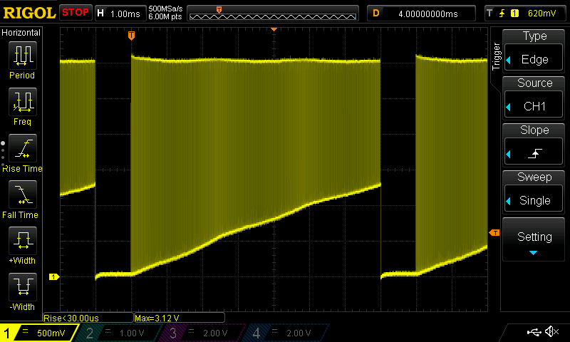
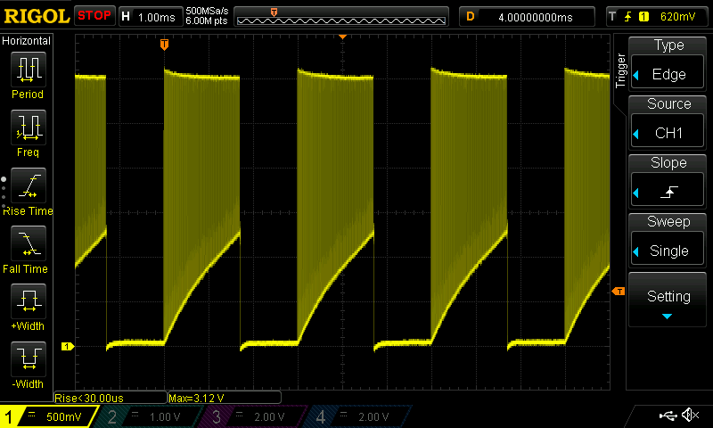
Here’s the voltage on the sense pad (click to enlarge). The bottom of the waveform is the voltage of the sampling capacitor which the pad is connected to after each charge cycle. The “wobbliness” of the longer waveform is caused by the spread spectrum feature of the touch controller, which slightly varies the pulse lengths to aid noise immunity and reduce EMI.
Here’s a detail of the charging spikes. You can see very quick exponentials at the edges as the charge flows between the capacitors or the sampling pad charges.
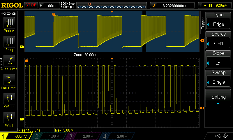
What happens when you use more than one touch sense group at once? Surprisingly, the pulses don’t stop, but rather continue until all the sampling capacitors reach their threshold voltages. The counter is frozen upon reaching the threshold, so this doesn’t really matter, it only slightly increases the power consumption and looks funny:
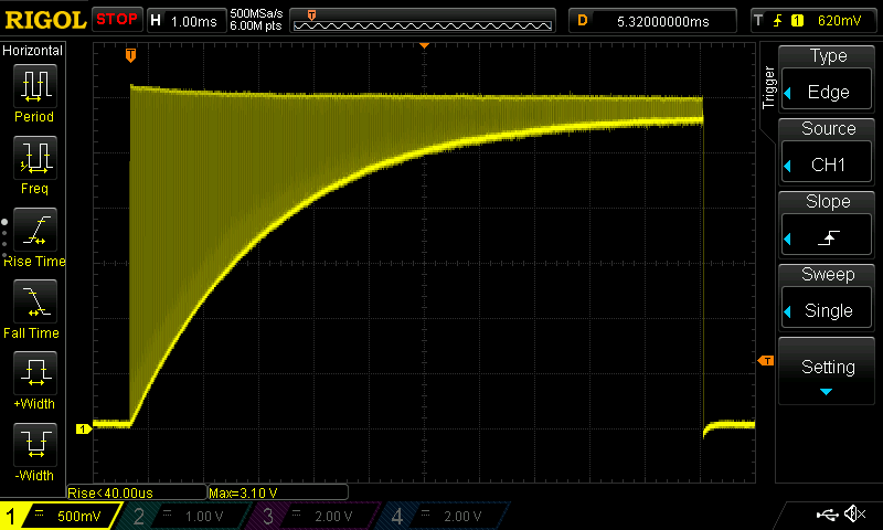
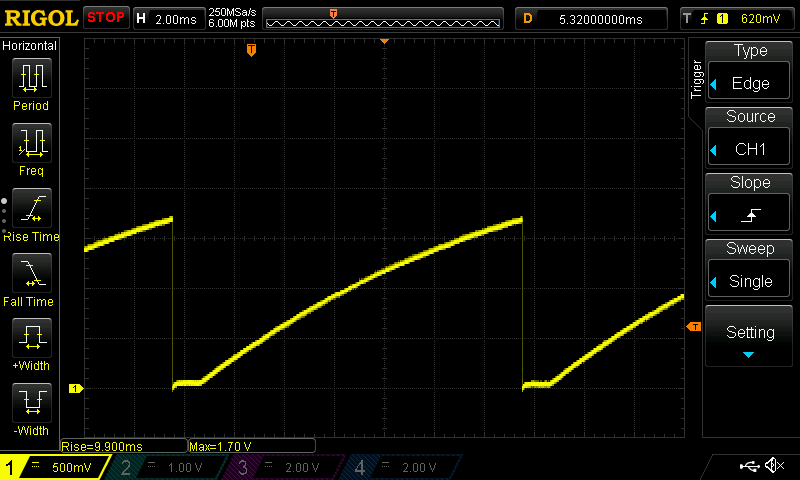
Finally, here’s a snapshot of the sampling capacitor voltage with only one group connected. The threshold appears to be 1.7 V.